Crossflow membrane filtration: Difference between revisions
imported>Justin D. Finkle No edit summary |
imported>Daniel Mietchen m (Crossflow Membrane Filtration moved to Crossflow membrane filtration: as per CZ:Naming conventions) |
Revision as of 14:44, 17 December 2010
Crossflow filtration is a term used to refer to a membrane filtration technique in which feed flows parallel to the membrane, rather than perpendicular to the membrane as in conventional filtration.[1] It is typically characterized by having high tangential fluid velocity and a low velocity normal to the membrane. Crossflow filtration is used in many applications of downstream processing including food processing, pharmaceutical production, and cell separation. This type of separation is typically used because of it is simple, cost effective, and has high throughput rates.
Comparison with conventional filtration
In an ideal crossflow filtration system, the flux of permeate through the membrane will reach a steady state. This allows for much easier continuous removal of the target material when compared with conventional filtration.
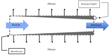
In practical applications, though, a cake builds up along the membrane. The cake increases in thickness through the length of the membrane filter until steady state is reached, as shown in the figure to the right.
Additionally, because the fluid flow is parallel to the membrane, rather than perpendicular to it as in conventional filtration systems, shear along the membrane prevents continual cake buildup. This contributes to the easy and continuous removal of the target material and reduces the need for cake washing. A boundary layer still develops along the membrane, but is usually very thin. Fouling of the membrane can still occur, along with concentration polarization, in which a gel layer forms and reduces transmembrane flux.
Membrane fouling
Though fouling is significantly reduced in crossflow membrane systems, as compared with conventional filtration systems, it is still a problem. Depending on the type of filter used and the pore sizes, different problems can arise.
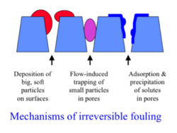
Concentration polarization can become exacerbated by gel formation in ultrafiltration systems, and microfiltration of suspended particles can create thick cake layers that reduce transmembrane flux.[1] Large, soft particles can adhere to the pores, smaller particles can clog pores, and precipitates can form on the pores all reducing the pore size available and reducing transmembrane flux. Various examples of pore plugging can be seen the figure on the left. Gel layer formation can sometimes be reduced by mechanical agitation. [2]
Typical Operation
Standard operating conditions and calculations vary depending upon the feed used, and are affected by how the feed interacts with the solution, the physical size and quantity of the target(s) of filtration in the feed, and whether the targets are dissolved or simply suspended in solution. Quantitatively, filtration flux (J) across the membrane can be calculated by dividing the driving force (∆Pm, typically the transmembrane pressure drop) by the overall membrane resistance (RG + RM). The gel resistance, RG, usually increases with time until the membrane is cleaned, and the resistance of the membrane, RM, is often assumed to stay constant. One of the main factors in the operation of a crossflow membrane filtration is the operating pressure. This accounts for a large portion of the energy costs associated with the filtration, and therefore a significant portion of the costs.
Dissolved Species
As the feed flows across the membrane,some molecules will be rejected by the membrane. When this occurs, a concentration gradient develops along the membrane in which molecules are locally in higher concentrations than that of the solution. Membranes with small enough pore sizes, such as those used in ultrafiltration, can even remove dissolved species causing the formation of a gel layer that impedes transmembrane flux. [2]
Suspended Species
Crossflow membrane filtration that involves suspended particles will generate a cake layer that is similar to the gel layer of an ultrafiltration system and is shown in Figure 1. [1] The cake layer will continue to thicken, constricting the fluid flow channel and reducing the transmembrane flux of the filtrate. Simultaneously, the shear forces at the edge of the fluid will increase due to the constricting channel diameter, preventing more cake deposition. An increase in the cake thickness will continue until steady state is reached. For particles greater than 1μm in diameter typical dissolved species flux equation is no longer valid and shear-induced diffusion theory created by Zydney and Colton can be used.[1]
Concentration Polarization
Concentration polarization along a membrane is experienced when the solute concentration at the membrane reaches elevated levels in comparison to the feed bulk fluid concentration. {ref name=Harrison2003/} The concentration gradient of dissolved species rejected at the membrane can be described by the following equation:
, where
δ = distance from the membrane
cm = concentration at the membrane
cδ = concentration at a distance δ from the membrane
J = transmembrane fluid flux
D = Diffusion coefficient
When concentration polarization reaches very high levels, it can cause precipitation of the solute, which forms a gel layer at the surface of the membrane. At times, this effect can become great enough that fluid flow across the membrane is significantly reduces. {ref name=Harrison2003/} Concentration polarization can be difficult to control, depending on the specific filtration, but it can be reduced in several ways. Running the filtration at a lower operation pressure, shortening the flow length, or creating turbulence by using thing flow channels or with additional mixing, can all reduce concentration polarization. Other more complicated methods of reducing concentration polarization include mechanical scouring, shaking, or skimming to remove the boundary layer. These are less ideal as they can effect the integrity of the membrane. Subscript text
Applications of crossflow filtration
Many different types of filtration exist that are specific to different particle sizes. Choosing the appropriate one depends on the target that is being selected for and the key impurities that will be removed. Different types of filters are shown in the table below and include: microfiltration, ultrafiltration, nanofiltration, and reverse osmosis.
| Size | Molecular Weight | Example Particle | Membrane Process |
|---|---|---|---|
| 100 μm | Pollen | Microfiltration | |
| 10μm | Starch | Microfiltration | |
| 1μm | Blood Cells, Bacteria | Microfiltration | |
| 100Å | 100,000 | Albumin, Pepsin | Ultrafiltration |
| 10Å | 1,000-10,000 | Vitamin B12, Glucose | Ultrafiltration, Nanofiltration |
| 1Å | Water, Sodium Chloride | Reverse Osmosis |
One particular type of crossflow membrane device is the hollow fiber membrane. In hollow fiber filter systems, the feed flow is run through many tiny hollow tubes and molecules are allowed to diffuse in and out, normal to the fluid flow through the tubes. This is commonly used in dialysis of human blood for patients with kidney problems.
Useful Equations
Transmembrane Flux
, where
J = transmembrane flux
ΔPm = transmembrane pressure drop
RG = gel resistance
RM = membrane resistance
As can be seen in the above equation, increasing the pressure, or decreasing resistance will increase the transmembrane flux. Pressure is usually in either pounds per square inch (psi), or SI units pascals (Pa). Transmembrane flux is typically in units of volume/area/time such as L1m-2hr-1. Resistances are experimentally derived and are given in units of inverse length. [1] Transmembrane flux can also be increased by changing the temperature or viscosity of the fluid.
Transmembrane Pressure
, where
Pi = initial feed pressure
Po = final outlet pressure
Pf = filtrate pressure
The transmembrane pressure can be changed by changing the operating parameters of the filtration. As with the transmembrane flux, temperature and viscosity can also effect the transmembrane pressure of the filtration. The pressure of the filtrate from the membrane is usually near atmospheric pressure. [2]


