Vacuum distillation/Citable Version: Difference between revisions
imported>D. Matt Innis (Vacuum distillation moved to Vacuum distillation/Draft: Approved) |
John Leach (talk | contribs) (removed link) |
||
| (10 intermediate revisions by 3 users not shown) | |||
| Line 1: | Line 1: | ||
# | {{subpages}} | ||
[[Image:Vacuum Column.jpg|right|thumb|183px|{{#ifexist:Template:Vacuum Column.jpg/credit|{{Vacuum Column.jpg/credit}}<br/>|}}Image 1: A [[vacuum]] distillation column in a petroleum refinery.]] | |||
[[Image:Vacuum Column.png|right|thumb|285px|{{#ifexist:Template:Vacuum Column.png/credit|{{Vacuum Column.png/credit}}<br/>|}}Image 2: Diagram of a vacuum column as used in [[Petroleum refining processes|petroleum refining]].]] | |||
[[Image:Vacuum distillation of DMSO at 70C.jpg|right|thumb|190px|{{#ifexist:Template:Vacuum distillation of DMSO at 70C.jpg/credit|{{Vacuum distillation of DMSO at 70C.jpg/credit}}<br/>|}}Image 3: [[Dimethyl sulfoxide]] boils at 189 °C at atmospheric pressure. Under vacuum, it distills at 70 °C.]] | |||
[[Image:Rotary Evaporation.png|right|thumb|350px|{{#ifexist:Template:Rotary Evaporation.png/credit|{{Rotary Evaporation.png/credit}}<br/>|}}Image 4: Rotary evaporation laboratory setup.]] | |||
[[Image:Perkin Triangle Distillation Setup.png|right|thumb|300px|{{Credit|Perkin Triangle Distillation Setup.png}}<center>Image 5: '''Perkin Triangle Distillation Setup''' | |||
{| class="wikitable" | |||
|- | |||
|1||Still pot||2||Fractionation column | |||
|- | |||
|3||Thermometer||4||Teflon valve | |||
|- | |||
|5||Cold finger||6||Coolant outlet | |||
|- | |||
|7||Coolant inlet||8||Teflon valve | |||
|- | |||
|9||Vacuum/Inert gas||10||Teflon valve | |||
|- | |||
|11||Distillate receiver | |||
|}</center>]] | |||
[[Image:Vacuum Distillation Setup.png|right|thumb|300px|{{Credit|Vacuum Distillation Setup.png}}<center>Image 6: '''Vacuum distillation with short-path distillation head''' | |||
{| class="wikitable" | |||
|- | |||
|1||Still pot||2||Short-path distillation head | |||
|- | |||
|3||Thermometer||4||Distillate receiver (Schlenk-type with side-arm) | |||
|- | |||
|5||Connection to vacuum or inert gas||6||Coolant inlet | |||
|- | |||
|7||Coolant outlet||8||Connection to vacuum or inert gas | |||
|}</center>]] | |||
'''Vacuum distillation''' is [[Continuous distillation|distillation]] of liquids performed at a [[pressure]] lower than [[atmospheric pressure]] to take advantage of the fact that reducing the pressure lowers the [[boiling point]] of liquids. This permits the distillation of liquids that are [[temperature]] sensitive and avoids any degradation of such liquids. | |||
== Vacuum distillation in petroleum refining == | |||
[[Petroleum]] [[crude oil]] is a complex mixture of hundreds of different [[hydrocarbon]] compounds generally having from 3 to 60 [[carbon]] [[atom]]s per [[molecule]], although there may be small amounts of hydrocarbons outside that range.<ref name=Handwerk>{{cite book|author=Gary, J.H. and Handwerk, G.E.|title=Petroleum Refining Technology and Economics|edition=2nd Edition|publisher=Marcel Dekker, Inc|year=1984|id=ISBN 0-8247-7150-8}}</ref><ref name=Leffler>{{cite book|author=Leffler, W.L. |title=Petroleum refining for the nontechnical person|edition=2nd Edition|publisher=PennWell Books|year=1985|id=ISBN 0-87814-280-0}}</ref><ref>{{cite book|author=James G, Speight|title=The Chemistry and Technology of Petroleum|edition=Fourth Edition|publisher=CRC Press|year=2006|id=0-8493-9067-2}}</ref> The refining of crude oil begins with distilling the incoming crude oil in a so-called [[Petroleum refining processes#The crude oil distillation unit|''atmospheric distillation column'']] operating at pressures slightly above atmospheric pressure.<ref name=Handwerk/><ref name=Leffler/><ref name=Kister>{{cite book|author=Kister, Henry Z.|title=[[Distillation Design]]|edition=1st Edition |publisher=McGraw-Hill|year=1992|id=ISBN 0-07-034909-6}}</ref> | |||
In distilling the crude oil, it is important not to subject the crude oil to temperatures above 370 to 380 °C because the high [[molecular weight]] components in the crude oil will undergo [[thermal cracking]] and form [[petroleum coke]] at temperatures above that. Formation of coke would result in plugging the tubes in the [[furnace]] that heats the feed stream to the crude oil distillation column. Plugging would also occur in the [[piping]] from the furnace to the distillation column as well as in the column itself. | |||
The constraint imposed by limiting the column inlet crude oil to a temperature of more than 370 to 380 °C yields a residual oil from the bottom of the atmospheric distillation column consisting entirely of hydrocarbons that boil above 370 to 380 °C. | |||
To further distill the residual oil from the atmospheric distillation column, the distillation must be performed at [[absolute pressure]]s as low as 10 to 40 [[mmHg]] (also referred to as [[Torr]]) so as to limit the operating temperature to less than 370 to 380 °C. | |||
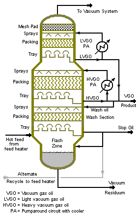
Image 1 is a photograph of a large vacuum distillation column in a petroleum refinery and Image 2 is a process diagram of a petroleum refinery vacuum distillation column that depicts the internals of the column. | |||
The 10 to 40 mmHg absolute pressure in a vacuum distillation column increases the volume of vapor formed per volume of liquid distilled. The result is that such columns have very large diameters.<ref>Karl Kolmetz, Andrew W. Sloley et al (2004), ''Designing Distillation Columns for Vacuum Service'', 11th India Oil and Gas Symposium and International Exhibition, September 2004, [[Mumbai]], [[India]] (also published in ''Hydrocarbon Processing'', May 2005)</ref> | |||
Distillation columns such those in Images 1 and 2, may have diameters of 15 meters or more, heights ranging up to about 50 meters, and feed rates ranging up to about 25,400 cubic meters per day (160,000 barrels per day). | |||
The vacuum distillation column internals must provide good vapor-liquid contacting while, at the same time, maintaining a very low pressure increase from the top of the column top to the bottom. Therefore, the vacuum column uses [[Theoretical plate|distillation tray]]s only where withdrawing products from the side of the column (referred to as ''side draws''). Most of the column uses [[Packed bed|packing material]] for the vapor-liquid contacting because such packing has a lower pressure drop than distillation trays. This packing material can be either [[Packed bed|structured sheet metal]] or randomly dumped packing such as [[Packed bed|Raschig rings]]. | |||
The absolute pressure of 10 to 40 mmHg in the vacuum column is most often achieved by using multiple stages of steam jet ejectors. <ref>[http://www.graham-mfg.com/ejphotos.html Photo gallery] (from website of Graham Manufacturing Company)</ref> | |||
Many industries, other than the petroleum refining industry, use vacuum distillation on a much a smaller scale. | |||
==Laboratory-scale vacuum distillation== | |||
Laboratory-scale vacuum distillation, sometimes referred to as ''low temperature distillation'', is used when the liquids to be distilled have high [[atmospheric boiling points]] or undergo a chemical change at temperatures near their atmospheric boiling points.<ref>[http://www.epa.gov/esd/chemistry/vacuum/default.htm Vacuum Distillation: New Method for Analyzing Organic Chemicals in a Wide Array of Samples] ([[United States Environmental Protection Agency]])</ref><ref>[http://www.newton.dep.anl.gov/askasci/chem00/chem00635.htm What is vacuum distillation?] ([[Argonne National Laboratory]]'s NEWTON Ask-A-Scientist)</ref> | |||
Temperature sensitive materials (such as [[beta carotene]]) also require vacuum distillation to remove [[solvent]]s from the mixture without damaging the product. | |||
There many laboratory applications for vacuum distillation as well as many types of distillation setups and apparatuses. Image 3 is a photograph of a vacuum distillation setup in a laboratory. | |||
Safety is an important consideration when using glassware as part of the setups. All of the glass components should be carefully examined for scratches and cracks which could result in implosions when the vacuum is applied. Wrapping as much of the glassware with tape as is practical helps to prevent dangerous scattering of glass shards in the event of an implosion. | |||
===Rotary evaporation=== | |||
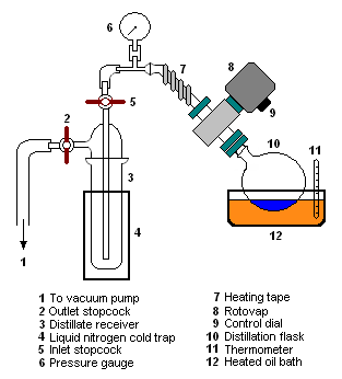
[[Rotary evaporation]]<ref>[http://www.chem.ubc.ca/courseware/235/danalabsess/rotovap.html Operation of a Rotary Evaporator (Rotovap)] (from the website of the [[University of British Columbia]])</ref> is a type of vacuum distillation apparatus used to remove bulk [[solvent]]s from the liquid being distilled. It is also used by environmental regulatory agencies for determining the amount of solvents in paint, coatings and inks.<ref>http://aqmd.gov/tao/methods/lab/303-91.pdf [[SCAQMD]] Test method 302-91]</ref> Image 4 is a diagram of one such setup. | |||
Rotary evaporation setups include an apparatus referred to as a ''Rotovap'' which rotates the distillation flask (sometimes called the ''still pot'') to enhance the distillation. Rotating the flask throws up liquid on the walls of the flask and thus increases the surface area for evaporation. | |||
Heat is often applied to the rotating distillation flask by partially immersing it in a heated bath of water or oil. Typically, the vacuum in such systems is generated by a water [[aspirator]] or a [[vacuum pump]] of some type. | |||
===Distillation of high-boiling and/or air sensitive materials=== | |||
Some compounds have high boiling point temperatures as well as being air sensitive. A simple laboratory vacuum distillation glassware setup can be used, in which the vacuum can be replaced with an inert [[gas]] after the distillation is complete. | |||
However, this is not a completely satisfactory system if it is desired to collect fractions under a reduced pressure. | |||
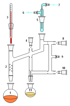
For better results or for very air sensitive compounds, either a Perkin triangle distillation setup or a short-path distillation setup can be used. | |||
====Perkin triangle distillation setup==== | |||
The Perkin triangle setup (Image 5 ) uses a series of [[Teflon]] valves to allow the distilled fractions to be isolated from the distillation flask without the main body of the distillation setup being removed from either the vacuum or the heat source, and thus can remain in a state of [[Reflux (distillation)|reflux]]. | |||
To do this, the distillate receiver vessel is first isolated from the vacuum by means of the Teflon valves. | |||
The vacuum over the sample is then replaced with an inert gas (such as [[nitrogen]] or [[argon]]) and the distillate receiver can then be stoppered and removed and removed from the system. | |||
====Vacuum distillation setup using a short-path head==== | |||
Vacuum distillation of moderately air/water-sensitive liquid can be done using standard Schlenk-line techniques (Image 6). | |||
When assembling the setup apparatus, all of the connecting lines are clamped so that they cannot pop off. | |||
Once the apparatus is assembled, and the liquid to be distilled is in the still pot, the desired vacuum is established in the system by using the vacuum connection on the short-path distillation head. Care is taken to prevent potential "bumping" as the liquid in the still pot degases. | |||
While establishing the vacuum, the flow of coolant is started through the short-path distillation head. Once the desired vacuum is established, heat is applied to the still pot. | |||
If needed, the first portion of distillate can be discarded by purging with inert gas and changing out the distillate receiver. | |||
When the distillation is complete: the heat is removed, the vacuum connection is closed, and inert gas is purged through the distillation head and the distillate receiver. While under the inert gas purge, remove the distillate receiver and cap it with an air-tight cap. The distillate receiver can be stored under vacuum or under inert gas by using the side-arm on the distillation flask. | |||
==References== | |||
{{reflist}} | |||
Latest revision as of 15:10, 10 February 2024
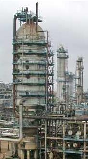
Image 1: A vacuum distillation column in a petroleum refinery.
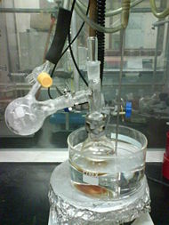
Image 3: Dimethyl sulfoxide boils at 189 °C at atmospheric pressure. Under vacuum, it distills at 70 °C.
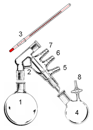
| 1 | Still pot | 2 | Short-path distillation head |
| 3 | Thermometer | 4 | Distillate receiver (Schlenk-type with side-arm) |
| 5 | Connection to vacuum or inert gas | 6 | Coolant inlet |
| 7 | Coolant outlet | 8 | Connection to vacuum or inert gas |
Vacuum distillation is distillation of liquids performed at a pressure lower than atmospheric pressure to take advantage of the fact that reducing the pressure lowers the boiling point of liquids. This permits the distillation of liquids that are temperature sensitive and avoids any degradation of such liquids.
Vacuum distillation in petroleum refining
Petroleum crude oil is a complex mixture of hundreds of different hydrocarbon compounds generally having from 3 to 60 carbon atoms per molecule, although there may be small amounts of hydrocarbons outside that range.[1][2][3] The refining of crude oil begins with distilling the incoming crude oil in a so-called atmospheric distillation column operating at pressures slightly above atmospheric pressure.[1][2][4]
In distilling the crude oil, it is important not to subject the crude oil to temperatures above 370 to 380 °C because the high molecular weight components in the crude oil will undergo thermal cracking and form petroleum coke at temperatures above that. Formation of coke would result in plugging the tubes in the furnace that heats the feed stream to the crude oil distillation column. Plugging would also occur in the piping from the furnace to the distillation column as well as in the column itself.
The constraint imposed by limiting the column inlet crude oil to a temperature of more than 370 to 380 °C yields a residual oil from the bottom of the atmospheric distillation column consisting entirely of hydrocarbons that boil above 370 to 380 °C.
To further distill the residual oil from the atmospheric distillation column, the distillation must be performed at absolute pressures as low as 10 to 40 mmHg (also referred to as Torr) so as to limit the operating temperature to less than 370 to 380 °C.
Image 1 is a photograph of a large vacuum distillation column in a petroleum refinery and Image 2 is a process diagram of a petroleum refinery vacuum distillation column that depicts the internals of the column.
The 10 to 40 mmHg absolute pressure in a vacuum distillation column increases the volume of vapor formed per volume of liquid distilled. The result is that such columns have very large diameters.[5]
Distillation columns such those in Images 1 and 2, may have diameters of 15 meters or more, heights ranging up to about 50 meters, and feed rates ranging up to about 25,400 cubic meters per day (160,000 barrels per day).
The vacuum distillation column internals must provide good vapor-liquid contacting while, at the same time, maintaining a very low pressure increase from the top of the column top to the bottom. Therefore, the vacuum column uses distillation trays only where withdrawing products from the side of the column (referred to as side draws). Most of the column uses packing material for the vapor-liquid contacting because such packing has a lower pressure drop than distillation trays. This packing material can be either structured sheet metal or randomly dumped packing such as Raschig rings.
The absolute pressure of 10 to 40 mmHg in the vacuum column is most often achieved by using multiple stages of steam jet ejectors. [6]
Many industries, other than the petroleum refining industry, use vacuum distillation on a much a smaller scale.
Laboratory-scale vacuum distillation
Laboratory-scale vacuum distillation, sometimes referred to as low temperature distillation, is used when the liquids to be distilled have high atmospheric boiling points or undergo a chemical change at temperatures near their atmospheric boiling points.[7][8]
Temperature sensitive materials (such as beta carotene) also require vacuum distillation to remove solvents from the mixture without damaging the product.
There many laboratory applications for vacuum distillation as well as many types of distillation setups and apparatuses. Image 3 is a photograph of a vacuum distillation setup in a laboratory.
Safety is an important consideration when using glassware as part of the setups. All of the glass components should be carefully examined for scratches and cracks which could result in implosions when the vacuum is applied. Wrapping as much of the glassware with tape as is practical helps to prevent dangerous scattering of glass shards in the event of an implosion.
Rotary evaporation
Rotary evaporation[9] is a type of vacuum distillation apparatus used to remove bulk solvents from the liquid being distilled. It is also used by environmental regulatory agencies for determining the amount of solvents in paint, coatings and inks.[10] Image 4 is a diagram of one such setup.
Rotary evaporation setups include an apparatus referred to as a Rotovap which rotates the distillation flask (sometimes called the still pot) to enhance the distillation. Rotating the flask throws up liquid on the walls of the flask and thus increases the surface area for evaporation.
Heat is often applied to the rotating distillation flask by partially immersing it in a heated bath of water or oil. Typically, the vacuum in such systems is generated by a water aspirator or a vacuum pump of some type.
Distillation of high-boiling and/or air sensitive materials
Some compounds have high boiling point temperatures as well as being air sensitive. A simple laboratory vacuum distillation glassware setup can be used, in which the vacuum can be replaced with an inert gas after the distillation is complete.
However, this is not a completely satisfactory system if it is desired to collect fractions under a reduced pressure.
For better results or for very air sensitive compounds, either a Perkin triangle distillation setup or a short-path distillation setup can be used.
Perkin triangle distillation setup
The Perkin triangle setup (Image 5 ) uses a series of Teflon valves to allow the distilled fractions to be isolated from the distillation flask without the main body of the distillation setup being removed from either the vacuum or the heat source, and thus can remain in a state of reflux.
To do this, the distillate receiver vessel is first isolated from the vacuum by means of the Teflon valves.
The vacuum over the sample is then replaced with an inert gas (such as nitrogen or argon) and the distillate receiver can then be stoppered and removed and removed from the system.
Vacuum distillation setup using a short-path head
Vacuum distillation of moderately air/water-sensitive liquid can be done using standard Schlenk-line techniques (Image 6).
When assembling the setup apparatus, all of the connecting lines are clamped so that they cannot pop off.
Once the apparatus is assembled, and the liquid to be distilled is in the still pot, the desired vacuum is established in the system by using the vacuum connection on the short-path distillation head. Care is taken to prevent potential "bumping" as the liquid in the still pot degases.
While establishing the vacuum, the flow of coolant is started through the short-path distillation head. Once the desired vacuum is established, heat is applied to the still pot.
If needed, the first portion of distillate can be discarded by purging with inert gas and changing out the distillate receiver.
When the distillation is complete: the heat is removed, the vacuum connection is closed, and inert gas is purged through the distillation head and the distillate receiver. While under the inert gas purge, remove the distillate receiver and cap it with an air-tight cap. The distillate receiver can be stored under vacuum or under inert gas by using the side-arm on the distillation flask.
References
- ↑ 1.0 1.1 Gary, J.H. and Handwerk, G.E. (1984). Petroleum Refining Technology and Economics, 2nd Edition. Marcel Dekker, Inc. ISBN 0-8247-7150-8.
- ↑ 2.0 2.1 Leffler, W.L. (1985). Petroleum refining for the nontechnical person, 2nd Edition. PennWell Books. ISBN 0-87814-280-0.
- ↑ James G, Speight (2006). The Chemistry and Technology of Petroleum, Fourth Edition. CRC Press. 0-8493-9067-2.
- ↑ Kister, Henry Z. (1992). Distillation Design, 1st Edition. McGraw-Hill. ISBN 0-07-034909-6.
- ↑ Karl Kolmetz, Andrew W. Sloley et al (2004), Designing Distillation Columns for Vacuum Service, 11th India Oil and Gas Symposium and International Exhibition, September 2004, Mumbai, India (also published in Hydrocarbon Processing, May 2005)
- ↑ Photo gallery (from website of Graham Manufacturing Company)
- ↑ Vacuum Distillation: New Method for Analyzing Organic Chemicals in a Wide Array of Samples (United States Environmental Protection Agency)
- ↑ What is vacuum distillation? (Argonne National Laboratory's NEWTON Ask-A-Scientist)
- ↑ Operation of a Rotary Evaporator (Rotovap) (from the website of the University of British Columbia)
- ↑ http://aqmd.gov/tao/methods/lab/303-91.pdf SCAQMD Test method 302-91]
- Pages using ISBN magic links
- Subpages
- Engineering Extra Subpages
- Chemistry Extra Subpages
- Chemical Engineering Subgroup Citable Versions
- Engineering Approved Extra Subpages
- Chemistry Approved Extra Subpages
- Citable versions of articles
- Engineering Citable Version Subpages
- Chemistry Citable Version Subpages
- All Content
- Engineering Content
- Chemistry Content
- Chemical Engineering tag
